


Engineered
Class Chains


Chain Resources
Contact Us
H Type
Drag Chains
- Overview
- Material
- Assembly
- Interchangeability
- Application
- Operation
- Specifications
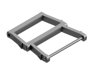

H type drag chains have links designed to operate in troughs or runways, in single or multiple strands. The underside of the links are broad to provide liberal wear surface. They are designed for heavy-duty operation imposed by drag conveyor service such as moving sawdust, refuse, fine coal, ash and other material in places where an economical installation is required.
Industries


Links are cast of high grade Duramal. Duramal is a heat treated copper bearing malleable iron having greater strength and superior resistance to wear and abrasion. Pins are heat treated.
Riveted construction is furnished unless cottered construction is requested.
H type drag chains are interchangeable with other standard makes of corresponding sizes and numbers.
H type drag chains are designed for heavy-duty operation imposed by drag conveyor service. It is usually dragged in troughs and used for moving sawdust, refuse, fine coal, ash and other materials in places where an economical installation is required. Multiple strands may be used to handle larger capacities.
The maximum speed recommended is 100 FPM. Maximum chain speed depends upon size of sprockets. For Conveyor Service see Table 2, Section A.

H Type Drag Chains Product Specifications
Product Information
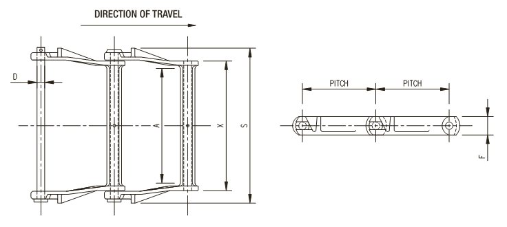
Dimensions are in inches unless otherwise noted.
Dimensions:
Product Chart:
Swipe to See More
| Chain No. | Average Pitch Inches | Approx. Links in 10 feet | Average Weight Per Ft. Lbs. | Dimensions in Inches | Attachment Numbers | ||||||
| Average Ultimate Strength in Lbs. | Rated Working Load in Lbs. | Barrel Length | Sidebar Width | Max. Spkt. Width | Pin Dia. | Overall Width | |||||
| Duramal | Duramal | X | F | A | D | S | |||||
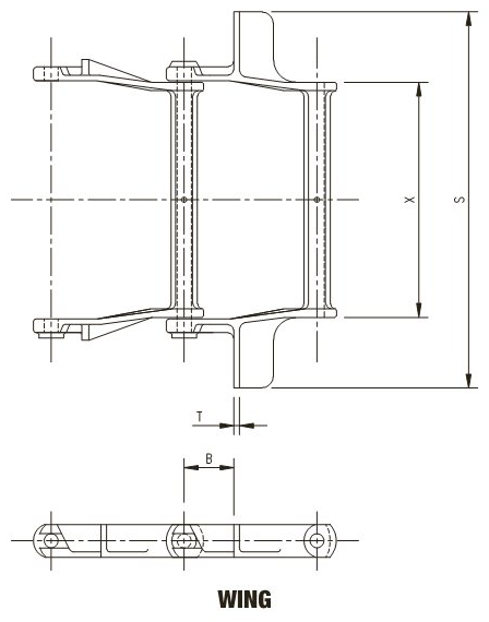
| H102 | 5 | 24 | 10.7 | 35,000 | 5,830 | 7 3/4 | 1 1/2 | 6 3/8 | 5/8 | 9 7/8 | WING |
| H104P | 6 | 20 | 8 | 35,000 | 5,830 | 5 5/16 | 1 1/2 | 4 1/8 | 5/8 | 7 11/16 | C4, WING |
| H104W | 6 | 20 | 8 | 35,000 | 5,830 | 5 5/16 | 1 1/2 | 4 1/8 | 5/8 | 7 3/8 | |
| H110 | 6 | 20 | 13.3 | 35,000 | 5,830 | 10 5/8 | 1 1/2 | 9 | 5/8 | 12 11/16 | C1, C3, WING |
| H112 | 8 | 15 | 10.8 | 35,000 | 5,830 | 10 5/8 | 1 1/2 | 9 | 5/8 | 12 3/4 | WING |
| H113 | 6 | 20 | 16.7 | 37,500 | 6,400 | 10 5/8 | 1 9/16 | 9 | 3/4 | 12 3/4 | |
| H116 | 8 | 15 | 14.6 | 35,000 | 5,830 | 14 7/16 | 1 5/8 | 12 1/2 | 5/8 | 16 11/16 | |
| H120 | 6 | 20 | 18.5 | 47,500 | 7,920 | 10 1/8 | 2 | 8 3/4 | 3/4 | 12 3/4 | |
| H480 | 8 | 15 | 18.1 | 50,000 | 8,330 | 12 11/16 | 2 | 11 1/8 | 3/4 | 16 | |
Dimensions are in inches unless otherwise noted.
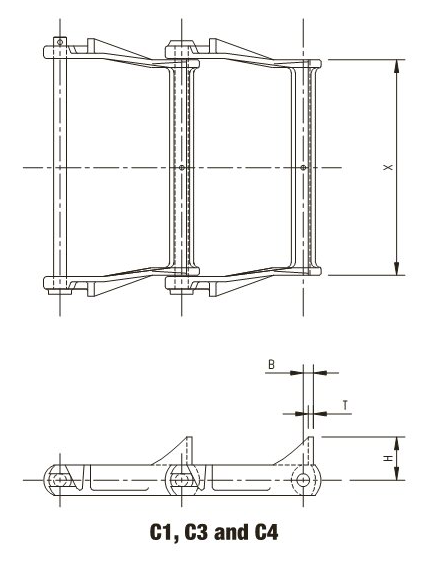
Select an attachment below:
 Click to view 3D
| Chain No. | B | H | T | X | Weight Per Foot-Lbs. |
|---|---|---|---|---|---|
| H110 | 1/2 | 2 1/8 | 1/4 | 10 5/8 | 14.6 |

Select a chain below:


Accessories

Master Catalog

The Webster Chain Wizard is a tool designed to help you identify or select a chain.

What Are You Looking For?

Find Out More
Contact Us
 Need Help!
Need Sales Support? Contact the Sales group at
sales@websterchain.com
Need Engineering Support? Contact the Engineering group at
engineeringsupport@websterchain.com
Give Us a Call - (800) 243-9327
Conversation
Deanna
Lorem ipsum dolor sit amet, consectetur adipisicing elit. Qui officia deserunt mollit anim id est laborum. Fugiat quo voluptas nulla pariatur?
Jamie
Lorem ipsum dolor sit amet, consectetur adipisicing elit. Qui officia deserunt mollit anim id est laborum. Fugiat quo voluptas nulla pariatur?